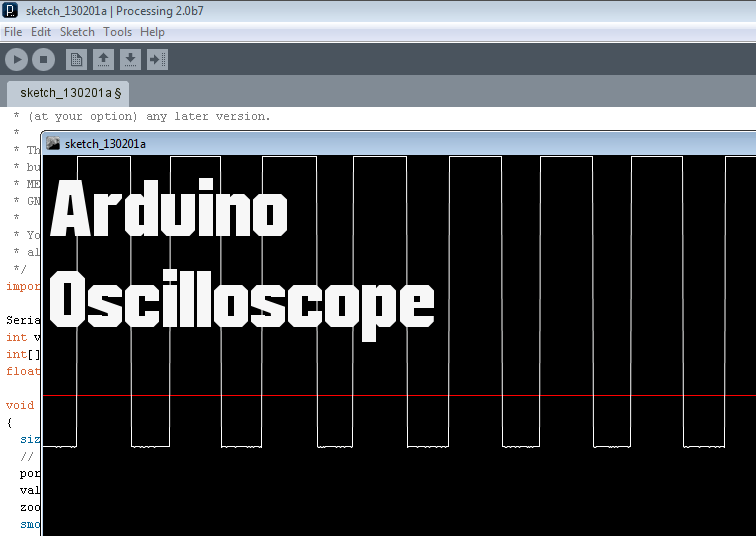
¿Alguna vez has querido utilizar un osciloscopio pero no puedes permitirte uno? ¡No te preocupes! Con Arduino, el osciloscopio del pobre, podrás crear tu propio dispositivo de monitoreo de señales electrónicas de forma económica y sencilla. Descubre en este artículo cómo puedes aprovechar al máximo esta plataforma de código abierto para tus proyectos electrónicos. ¡No te lo pierdas!
¡Hoy estoy hablando de un proyecto realmente bueno que puedes hacer con tu Arduino! Esta es la mejor manera de tener a mano un osciloscopio barato. No escribí este código, pero lo encontré en Internet hace algún tiempo y decidí compartir este gran proyecto. Empecemos…

Primero, descargue Processing. Es gratis Haga click aquí para descargar. No necesitas instalar nada, se ejecuta como el IDE de Arduino.
Sube este código a tu Arduino
/*
  Complete project details: https://randomnerdtutorials.com/arduino-poor-mans-oscilloscope/
*/

#define ANALOG_IN 0

void setup() {
  Serial.begin(9600);
  //Serial.begin(115200);
}

void loop() {
  int val = analogRead(ANALOG_IN);
  Serial.write( 0xff );
  Serial.write( (val >> 8) & 0xff );
  Serial.write( val & 0xff );
}
Luego ejecute este código en el IDE de procesamiento.
/*
 * Oscilloscope
 * Gives a visual rendering of analog pin 0 in realtime.
 *
 * This project is part of Accrochages
 * See http://accrochages.drone.ws
 *
 * (c) 2008 Sofian Audry ([email protected])
 *
 * This program is free software: you can redistribute it and/or modify
 * it under the terms of the GNU General Public License as published by
 * the Free Software Foundation, either version 3 of the License, or
 * (at your option) any later version.
 *
 * This program is distributed in the hope that it will be useful,
 * but WITHOUT ANY WARRANTY; without even the implied warranty of
 * MERCHANTABILITY or FITNESS FOR A PARTICULAR PURPOSE.  See the
 * GNU General Public License for more details.
 *
 * You should have received a copy of the GNU General Public License
 * along with this program.  If not, see <http://www.gnu.org/licenses/>.
 */
import processing.serial.*;

Serial port;  // Create object from Serial class
int val;      // Data received from the serial port
int[] values;
float zoom;

void setup()
{
  size(1280, 480);
  // Open the port that the board is connected to and use the same speed (9600 bps)
  port = new Serial(this, Serial.list()[0], 9600);
  values = new int[width];
  zoom = 1.0f;
  smooth();
}

int getY(int val) {
  return (int)(height - val / 1023.0f * (height - 1));
}

int getValue() {
  int value = -1;
  while (port.available() >= 3) {
    if (port.read() == 0xff) {
      value = (port.read() << 8) | (port.read());
    }
  }
  return value;
}

void pushValue(int value) {
  for (int i=0; i<width-1; i++)
    values[i] = values[i+1];
  values[width-1] = value;
}

void drawLines() {
  stroke(255);

  int displayWidth = (int) (width / zoom);

  int k = values.length - displayWidth;

  int x0 = 0;
  int y0 = getY(values[k]);
  for (int i=1; i<displayWidth; i++) {
    k++;
    int x1 = (int) (i * (width-1) / (displayWidth-1));
    int y1 = getY(values[k]);
    line(x0, y0, x1, y1);
    x0 = x1;
    y0 = y1;
  }
}

void drawGrid() {
  stroke(255, 0, 0);
  line(0, height/2, width, height/2);
}

void keyReleased() {
  switch (key) {
    case '+':
      zoom *= 2.0f;
      println(zoom);
      if ( (int) (width / zoom) <= 1 )
        zoom /= 2.0f;
      break;
    case '-':
      zoom /= 2.0f;
      if (zoom < 1.0f)
        zoom *= 2.0f;
      break;
  }
}

void draw()
{
  background(0);
  drawGrid();
  val = getValue();
  if (val != -1) {
    pushValue(val);
  }
  drawLines();
}
Y luego lo único que tienes que hacer es conectar el pin analógico 0 del Arduino a la señal que quieres leer.
¡Y listo!
Piezas requeridas
- Arduino UNO – leer Los mejores kits de inicio de Arduino
- 1x placa de pruebas
- 1xLED
- 1x resistencia de 10k
- Resistencia de 1 × 4,7k
- 1x resistencia de 1k
- 1 condensador electrolítico de 100 nF.
- Cables de puente
Esquema
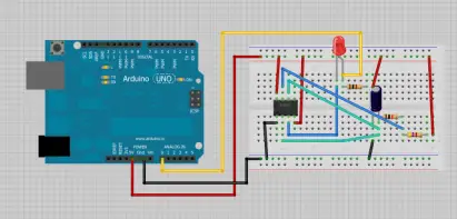
Este es el circuito que mediré, es un circuito temporizador 555 simple… que hace parpadear un LED.

Mira el vídeo de demostración
Gracias por leer. Puedes contactar conmigo dejando un comentario. Si te gusta esta publicación, probablemente también te gustarán las siguientes, así que apóyame suscribiéndote a mi blog y a mi blog. Sitio de Facebook.
[automatic_youtube_gallery type=»search» search=»Arduino: el osciloscopio del pobre
» limit=»1″]
Arduino: el osciloscopio del pobre
Hoy hablaré sobre un proyecto realmente interesante que puedes realizar con tu Arduino. Esta es la mejor manera de tener un osciloscopio económico a tu alrededor. No escribí este código, lo encontré en Internet hace un tiempo y decidí compartir este increíble proyecto. ¡Comencemos!
Pasos a seguir
- Descarga Processing. Es gratuito: Descarga aquí. No necesitas instalar nada, se ejecuta como el IDE de Arduino.
- Sube este código a tu Arduino:
View raw code
Luego, ejecuta este código en el IDE de Processing. Este proyecto te permitirá tener una representación visual del pin analógico 0 en tiempo real.
View raw code
Después, solo necesitas conectar el pin analógico 0 de Arduino a la señal que deseas leer. ¡Y listo!
Partes requeridas
- Arduino UNO
- 1x Protoboard
- 1x LED
- 1x Resistencia de 10k ohmios
- 1x Resistencia de 4.7k ohmios
- 1x Resistencia de 1k ohmios
- 1x Capacitor electrolítico de 100nF
- Cables puente
Aquí tienes el esquemático del circuito que estaré midiendo, es un circuito simple con un temporizador 555 que hace parpadear un LED.
Video de demostración
Puedes ver en acción este proyecto en el siguiente video:
¡Gracias por leer! Puedes contactarme dejando un comentario. Si te gustó esta publicación, probablemente te gustarán las siguientes, así que por favor, apóyame suscribiéndote a mi blog y a mi página de Facebook.
